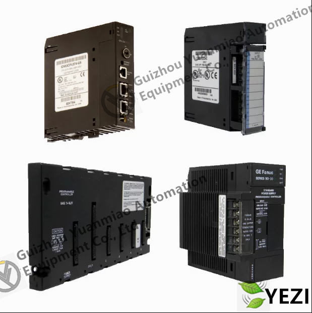
Attention: Due to the large number of products from our company, the pictures cannot match each other. Please contact me to confirm the actual product!
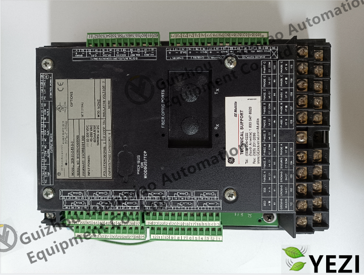
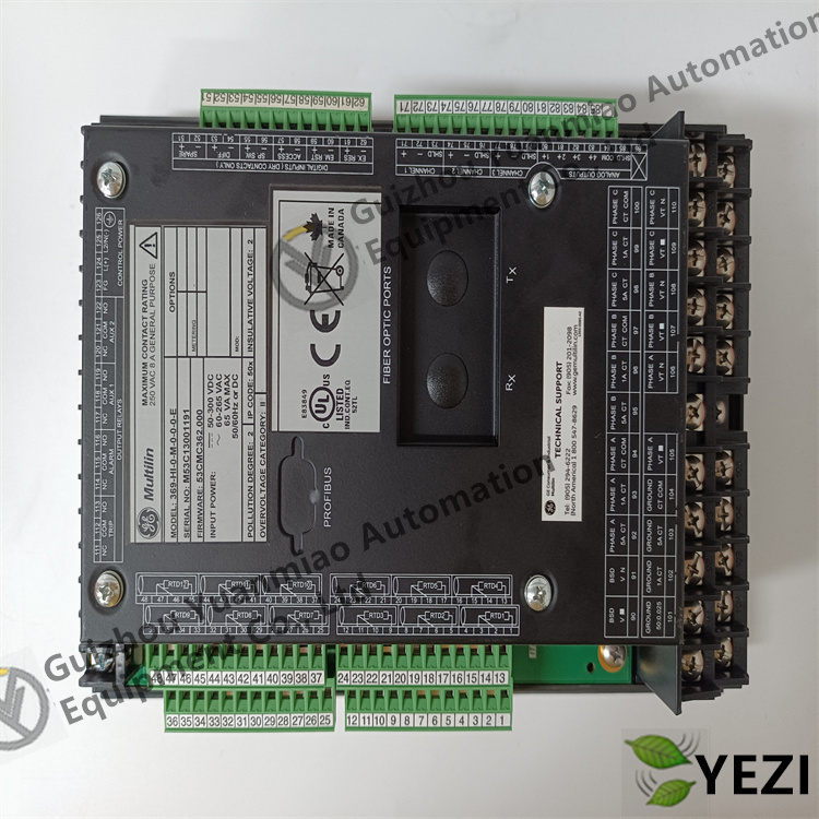
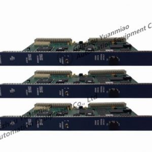
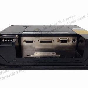
369-HI-0-M-0-0-0-E is a model of 369 Series Protection Relay manufactured by GE (General Electric). It is mainly used for the protection and monitoring of motors, transformers, and other equipment in power systems. Currently, there is no separate user manual for this model available in public channels. However, you can refer to the general manual of GE 369 Series Protection Relays (such as 369 Motor Management Relay User Manual released by GE official), which covers the common functions, operations, and technical information of this series of products. The following is relevant information sorted out based on the series characteristics, which can be used as a reference for use:
- Model Interpretation: In the 369 series models, suffixes such as “HI” usually represent specific configurations (e.g., interface type, function options, etc.). 369-HI-0-M-0-0-0-E is mainly positioned as a motor management relay with protection, monitoring, and control functions.
- Core Purpose: It is used for protection against overload, overcurrent, undervoltage, locked rotor, ground fault, etc., in low-voltage motors. It also supports motor operating status monitoring (such as current, temperature, power, etc.) and remote control.
-
Protection Functions
- It provides various motor protection logics, including:
- Overload protection (based on thermal simulation curves, trip thresholds can be set)
- Overcurrent protection (instantaneous and time-delay overcurrent to deal with faults such as short circuits)
- Undervoltage/overvoltage protection (monitors abnormal power supply voltage)
- Locked rotor protection (detects locked rotor status during motor start-up or operation)
- Ground fault protection (detects leakage current to ground)
-
Monitoring and Metering
- Real-time monitoring of motor operating parameters: three-phase current, voltage, power, power factor, temperature (external sensors required), etc.
- Records fault events (such as fault type, occurrence time, parameters at the time of fault) and supports historical data query.
-
Control and Communication
- Supports local/remote control of motor start and stop (via relay output or communication commands).
- Communication interface: Usually equipped with RS485 (Modbus RTU protocol), which can be connected to SCADA or PLC systems to realize data upload and remote configuration.
-
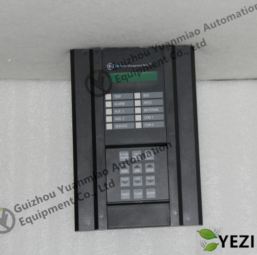
Display and Operation
- Equipped with a small display screen and buttons, which can be used to view parameters, set protection thresholds, reset faults, etc. on site.
-
Installation and Wiring
- Installation environment: It is recommended to install it in a control cabinet. The operating temperature range is usually -25℃~+70℃. Avoid dust, humidity, and severe vibration.
- Wiring requirements: The main circuit (current and voltage input) should be wired according to the rated specifications. The control circuit (auxiliary power supply, output contacts) should pay attention to insulation and capacity matching. For the specific wiring diagram, you can refer to the terminal definition in the 369 series general manual.
-
Parameter Setting
- Configure protection parameters (such as overload curves, current transformer ratio, trip delay, etc.) through panel buttons or supporting software (such as GE’s TripLink).
- It is necessary to adjust the protection threshold according to the rated parameters of the motor (power, rated current, starting method, etc.) to ensure that the protection is reliable and avoids misoperation.
-
Maintenance and Troubleshooting
- Daily inspection: Check if there is any fault alarm on the display screen (such as “OVERLOAD”, “GROUND FAULT”, etc.) and check if the wiring terminals are loose.
- Common fault handling: If there is a false trip, you can query the fault cause through the event record (such as whether the actual current exceeds the limit); if the communication is interrupted, check the communication wiring and protocol parameters (baud rate, address, etc.).
Related products:
369-HI-0-M-F-E-0 Motor management relay
369-HI-R-M-F-E-H-E Integrated relay protector
GE 369-HI-R-M-0-0-0-E electric machinery
[Disclaimer]
Our company sells new products and discontinued products, and purchases such special products through independent channels. Guizhou Yuanmiao Automation Equipment Co., Ltd. is not an authorized distributor, distributor or representative of the featured products of this website. All product names/product images, trademarks, brands and microlabels used on this website are the property of their respective owners. Product descriptions, descriptions or sales with these name images, trademarks, brands and logos are for identification purposes only and do not represent any association or authorization with any right holders.
")


Reviews
There are no reviews yet.